Study of the Carbothermal Reduction of Self-Reducing Briquettes Developed with Iron Ore Fines, Charcoal and Silica Fume Residues (1)
1. Introduction
The formation of solid residues in the industry has become the current agenda of several scientific studies, in response to the environmental, social and economic impacts related to disposing of such potentially harmful waste, and also due to the pressures of society worldwide. Consequently, the various metallurgical and process industries are taking preventive measures to mitigate the problem, and to comply with current laws and regulations. It is important to develop alternative processes that enable a sustainable utilization of the residues generated in the different production processes.
Ferrosilicon (FeSi) is an alloy of iron and silicon, and its production process involves the carbothermic reduction of these two raw materials in a submerged electric arc furnace (SAF). In steelmaking, FeSi acts as a source of silicon to reduce metals from their oxides and as a deoxidizing agent in the production of steel and other types of ferroalloys. It is also a raw material in the manufacture of alloys resistant to corrosion and high temperatures, used in electromotors and transformers.
In ferrosilicon (FeSi) production, the raw materials used are: (i) quartz, as the main silicon (Si) supplier; (ii) iron ore, as a source of iron (Fe); and (iii) carbon (C), as the main reducer, with charcoal being the most frequently used in Brazil. The raw materials are fed into the furnace around the electrodes, and are then reduced at temperatures around 800 °C to 2000 °C. Ferrosilicon is produced by processing quartz rock (SiO2) with carbon as a reducing agent, according to Equation (1).

The generation of waste from this production process is often related to the formation of fines due to the handling and/or transformation processes of raw materials [6,12]. Thus, the fractions of quartz fines, iron ore and charcoal are residual materials generated due to physical degradation, which is also related to the morphological characteristics of the raw materials used in the process [9,13]. It is recommended to remove such fines by sieving before introducing the calculated load. The fines will severely affect the permeability in the furnaces and thus cause an inadequate distribution and insufficient percolation of gases. This will again lead to high losses of gases and a low Si-yield.
During the FeSi production process, silicon monoxide gas (SiO) is formed. SiO reacts with O2(g) at the top of the furnace charge and the two form silicon dioxide (SiO2), also known as silica fume. The particles of silica fume are removed and collected by the off-gas systems to reduce atmospheric emissions of the submerged electric arc furnaces in accordance with environmental legislation. If released into the atmosphere, this particulate material is considered to be a primary pollutant. The waste consists of spherical particles of amorphous silica with an average diameter of 0.10 micrometers and apparent density ranging from 130 to 430 kg/m3.
Due to the need for adequate environmental disposal of iron ore fines; charcoal fines and silica fume, alternatives for commercialization should be explored. As a last resort, they should be deposited in an industrial landfill. As the market utilisation of these waste products is limited, the alternative, reusing them as components for the manufacture of self-reducing briquettes, was considered. Whether or not these briquettes could be used in an SAF depends on their behaviour in the furnace. Consequently, it is important to determine the physical and metallurgical properties of the input materials, in order to predict their behaviour during handling, and the reduction inside the furnaces.
It should be emphasized that the sizing of the input load in the mass balance would be calculated paying attention to the efficient operation in SAFs, the concordant proportion of silica and iron ore in relation to the reducing agent (charcoal), in addition to the adequate energy input to promote the reduction of oxides. Thus, in relation to the operability of agglomerates in SAFs, the concept of reprocessing depends intrinsically on issues related to the establishment and maintenance of thermodynamics, in consensus with a favourable kinetics of the reactions predominant in the process. Thus, research on the physical and metallurgical properties of the input materials is of paramount importance, as it indicates their behaviour during the handling and reduction processing within the furnaces.
The present work investigated the physical behaviour and reduction of self-reducing briquettes produced with silica fume, iron ore fines and charcoal fines, and verified the products obtained during the carbothermal reduction of these FeSi wastes. The intention of using these self-reducing briquettes as a complementary charge, together with the raw materials required for FeSi production, would be to promote a sustainable production cycle for the ferroalloy segment.
It should be noted that the raw materials are sampled from the industry, while the production of briquettes was on a laboratory scale. The composition of the self-reducing briquettes was found through stoichiometric calculations of the simplified mass balance to produce 1 ton of FeSi75. The binders used and selected for the manufacture of the self-reducing briquettes were hydrated lime, Portland cement, and sodium silicate. The proportions of binders were 0.00%; 2.50%; 5.00%; 7.50% and 10.00%, based on existing research. The sum of the waste and binders used covers 100%, with water used additionally, adopting four arbitrary levels of moisture for the tests: 0.00%; 5.00%; 10.00% and 15.00%.
Finally, the performance of the briquettes was studied in relation to their physical behaviour after a curing time of 10 days. They were subjected to density and shatter tests, and were tested for porosity and disintegration during thermal heating. Using pre-established points which are based on the scientific literature, they were then selected for the high temperature reduction tests. Subsequently, the metallic or carbonaceous phases of the briquettes were determined.
2. Materials and Methods
2.1. Sampling and Sample Preparation
The waste samples from the FeSi production process which were used as raw materials in the production of the self-reducing briquettes were provided by a FeSi75% industrial producer, located in the State of Minas Gerais in Brazil. Samples were collected from wastes provided by this metallurgic plant using standard ABNT NBR 10004:2004. The size distribution of the fines was <3.00 mm. The waste samples were chosen for the sampling by the method of quarters in conical piles, until fractions for characterization and production of briquettes were obtained.
2.2. Sample Characterization of Wastes and Composition of Self-Reducing Briquettes
For the characterization of the waste fines, granulometric analyses were performed of dry samples of iron ore and charcoal fines. By using a sieving technique, the fines passed through a series of sieves with 3.35 mm, 2.00 mm, 1.00 mm, 0.50 mm, 0.25 mm, 0.15 mm, 0.075 mm and 0.038 mm opening. The granulometric characterization of the silica fume was carried out using dry samples and it was analysed by the laser diffraction technique (Mastersizer 3000, Malvern Panalytical, Malvern, UK).
Then, chemical analyses were done using the inductively coupled plasma spectrometry technique (ICP-OES, Perking Elmer Optima, 7300 DV). Determination of moisture, loss by calcination (PPC) and immediate analysis (content of moisture, volatiles, ash, and fixed carbon) in the charcoal fines were performed.
The formulation for the self-reducing briquettes was determined by the stoichiometric calculations of the simplified mass balance to produce 1 ton of FeSi75. Effectively, to know the amount of raw material needed to produce 1 ton of FeSi75, it is necessary to know the chemical composition of the raw materials and the alloy to be produced. In this perspective, as described in literature [9,15,16], to produce FeSi alloys, the control of the mixtures should be performed in a quantitative (amount of carbon introduced in the carbon/quartz ratio) and qualitative way (quartz nature, reactivity, particle size distribution of the raw materials, and porosity of the charge).
The production of self-reducing briquettes reported in this work aims to use a high fraction of silica fume in the mixture of the briquettes, increasing its reactivity, and reducing waste in the production process. The silica fume will replace the quartz as the raw material, supplying SiO2 for the self-reducing briquettes. The percentage composition of waste to produce self-reducing briquettes is described in Table 1.
Table 1. Composition of self-reducing briquettes
| Material | Quantitative Composition of Burden (kg) | Proportion in the Briquettes (%) | Binders (%) |
|---|---|---|---|
| Silica fume | 178.57 | 43.72 | 0.00; 2.50; 5.00; 7.50; 10.00 |
| Ire ore fines | 131.36 | 32.16 | |
| Charcoal fines | 57.65 | 14.12 |
Binders were added to the mixture when necessary. These were discounted in the proportion of silica fume and when necessary, the addition was in the proportion of charcoal used in the mixture.
Three types of binders were used in the briquettes: Portland cement, hydrated lime, and sodium silicate. In addition, mixtures without binders were prepared. The addition of binders was considered necessary, so was initially performed with variations that occurred in the proportions of 0.00%; 2.50%; 5.00%; 7.50% and 10.00% based on studies related to the works.
In total, 13 different mixtures were prepared using silica fume, iron ore fines, charcoal fines, and binders, as shown in Table 2. To organize the various samples, they were labelled M1 through 13, where M stands for mixture, and the following number indicates the type of mixture. Four moisture levels were used for testing: 0.00%, 5.00%, 10.00% and 15.00%. When water was added to the mixtures, the briquettes were produced and labelled with the letters BM. As such, adding in the acronym BM, the numbering of the respective mixture from 1 to 13, and then the digit (−), the letter A representing the water and its addition percentage in numbering from 1 to 4, with the number 1 for 0.00%, the number 2 for 5.00%, the number 3 for 10.00% and the number 4 for 15.00%, representing the percentage of water added in the respective mixture, the labelling was completed. Thus, 52 treatments were investigated.
Table 2. Mixtures used in the briquetting process.
| Mix (M) | Percentage Composition of Blends | |||||
|---|---|---|---|---|---|---|
| Silica Fume (%) | Charcoal Fines (%) | Iron Ore Fines (%) | Binders (%) | Water (%) | ||
| M1 | 54.0 | 32.0 | 14.0 | - | 0.0 | |
| 5.0 | ||||||
| 10.0 | ||||||
| 15.0 | ||||||
| M2 | 51.5 | 32.0 | 14.0 | Portland cement | 2.5 | 0.0 |
| M3 | 49.0 | 32.0 | 14.0 | 5.0 | 5.0 | |
| M4 | 46.5 | 32.0 | 14.0 | 7.5 | 10.0 | |
| M5 | 44.0 | 32.0 | 14.0 | 10.0 | 15.0 | |
| M6 | 51.5 | 32.0 | 14.0 | Hydrated lime | 2.5 | 0.0 |
| M7 | 49.0 | 32.0 | 14.0 | 5.0 | 5.0 | |
| M8 | 46.5 | 32.0 | 14.0 | 7.5 | 10.0 | |
| M9 | 44.0 | 32.0 | 14.0 | 10.0 | 15.0 | |
| M10 | 51.5 | 32.0 | 14.0 | Sodium silicate | 2.5 | 0.0 |
| M11 | 49.0 | 32.0 | 14.0 | 5.0 | 5.0 | |
| M12 | 46.5 | 32.0 | 14.0 | 7.5 | 10.0 | |
| M13 | 44.0 | 32.0 | 14.0 | 10.0 | 15.0 | |
The mixtures were submitted to briquetting in a hydraulic press (with a maximum capacity of 10 t), using a cylindrical matrix and a compression piston. Approximately 30.00 g of each mix was inserted and placed inside the cylindrical matrix. The pressure of compaction, 5.00 t (77.52 MPa) was defined in preliminary tests of structural evaluation of the self-reducing briquettes. The compaction time was 60 s and the curing time at least 10 days. Five cylindrical briquettes were produced with each mixture in this way. Figure 1 shows an example of the cylindrical briquettes produced.
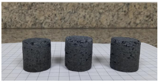
Figure 1. Self-reducing briquettes (BM12-A4) produced with sodium silicate binder.
2.3. Physical Characterization of Self-Reducing Briquettes
The knowledge of the structural resistance behaviour of the self-reducing briquettes was a prerequisite for the selection and eligibility of the briquettes. The structural resistance may also be linked with the kinetic and thermodynamic conditions that would promote the self-reduction [4,20,21,22,23,24,25]. Figure 2 shows the methodological flowchart with the experimentation tests and analyses to which these agglomerates were submitted. The lower range was stipulated for each experimental test and this criterion was considered as a selection filter of the treatments that would be submitted to the subsequent tests.
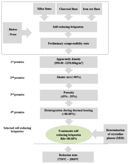
Figure 2. Flowchart of the experimental procedure and selection criteria applied.
2.3.1. Apparent Density
The apparent density was determined for a set of three briquettes for each sample produced, achieving an average between the three series. For the cylindrical briquettes, the apparent density was determined through an association between the mass and volume of each briquette.
2.3.2. Shatter Test (Adapted Methodology)
Methods of measuring the shatter resistance of self-reducing briquettes are described in ASTM D440:2002, ISO 616:1995 and JIS M8711:2011. Adhering to the described methodologies, the impact strength test consisted basically in submitting the briquettes to successive falls from a preliminary height of 0.30 m. Only the briquettes that obtained shatter resistance above 90% for the initial test were considered suitable for the sequence of tests involving falling from a height of 1.50 m.
The shatter tests simulated a similar fall of the raw materials from the conveyor belt to the surface in the SAFs. The shatter index was obtained by a series of five repetitions, for the 52 types of produced treatments, where the average was calculated. The resulting shatter index was the percentage in mass of the fraction passing 9.50 mm that was defined as the index of fines generation by slump. Being the percentage in mass of the passing fraction of the briquette (M1), in relation to the total mass of the sample of briquette tested (M). Equation (2) shows the calculation of the breakage index and Equation (3) the calculation for the determination of the shatter resistance (R):


2.3.3. Porosity
The porosity analyses were performed on the treatments of self-reducing briquettes that obtained results equal to or higher than 90% in the drop resistance tests (1.50 m). The porosity is an important parameter in the determination of the physical resistance and the electrical resistivity; thus, to reach the necessary resistivity (0.13 Ω/m) at 1200 °C, for the use of the aggregate in electric arc furnaces, the adequate porosity is 45–55%. For the analysis procedure, the gas pycnometry technique [Ultrapyc, model 5000, Anton Paar] was employed by injecting the inert gas (helium) to be absorbed on the surface of the samples. Equation (4) shows the calculation to determine the porosity of the self-reducing briquettes, where Vg: represents the geometric volume (g/cm3) and Vp: pycnometer volume (g/cm3):
Porosity:

2.3.4. Disintegration during Thermal Heating
The influence of temperature on the structural integrity of the self-reducing briquettes was analysed in those treatments that met the criteria of porosity between 45–55%. The proposed tests evaluated the physical characteristics of resistance to high temperature of briquettes, in a non-standardized test. The procedures for quantification of this test were based on the ISO 8371:2015 [30] and ISO 7215:2015 standards. For iron ore pellets for use in reduction reactors, the crackling index test is one of the main evaluations of the metallurgical characteristics of this ore. The tests were performed in a muffle furnace, with temperature variation from 0 °C to 1200 °C in 300 °C increments. The briquettes were weighed, before and after the preheating treatment, and then sieved in a granule sieve with a 9.50 mm mesh. The resistance to thermal heating was determined as the percentage material retained in the sieve, and this size mesh was taken as a reference because it is the minimum grain size for raw material in electric arc furnaces. Equation (5) shows the calculation used for determination of the resistance to degradation (Rdr) against the thermal gradient applied to the treatments of self-reducing briquettes M1. The mass of the material retained in mesh of 9.50 mm (g) and M the mass of the initial agglomerate (g):

Thus, only the self-reducing briquette treatments that presented Rdr values >80% were selected for evaluation of their reduction.
2.3.5. Determination of Crystalline Phases by X-ray Diffraction (XRD)
The samples of the treatments that obtained the value of Rdr >80% were submitted to the qualitative analyses by X-ray diffractometry (XRD) [Philips PANanalytical, model PW1710, UFMG]. CuKalpha radiation and monochromator in 0.06° (2θ) step were used, at 40 kV and 40 mA. The analysis method was based on the comparison of the values of interplanar distances and peak intensities in the diffractograms of the samples analysed, and a reference sample, using the standard PDF-2 Release 2010 database of the ICDD—International Centre for Diffraction Data and the software X’Pert HighScore PLUS version 4.0 (Almelo, The Netherlands).
2.4. Metallurgical Characterization of Self-Reducing Briquettes
The evaluations of the metallurgical behaviour are determining factors for the investigation of the metallic and carbonaceous phases of the self-reducing briquettes as a function of the experimental temperatures, as well as their self-reducing character. The criteria adopted as pre-established conditions for the selection of the treatments of the self-reducing briquettes conforms with the premises established for selection of the load in the SAF. Thus, to verify the reduction of the briquettes, they were subjected to reduction tests at different temperatures (Table 3). Subsequently, the remaining materials from these tests were analysed in SEM/EDS, to determine their composition and the individual phases presented.
Table 3. Experimental matrix for the reduction tests.
| Reduction Tests | Temperature (°C) | Time Interval (min.) | Time at Target Temperature (min.) | He (g) (L/min.) |
|---|---|---|---|---|
| 1 | 1500 | 00:25:00 | 30 | 0.1 |
| 1800 | 00:15:00 | |||
| 1800 | 00:30:00 | |||
| 25 | 00:30:00 | |||
| 2 | 1500 | 00:25:00 | 30 | 0.1 |
| 1850 | 00:15:00 | |||
| 1850 * | 00:30:00 | |||
| 25 | 00:30:00 | |||
| 3 | 1500 | 00:25:00 | 30 | 0.1 |
| 1750 | 00:15:00 | |||
| 1750 * | 00:30:00 | |||
| 25 | 00:30:00 | |||
| 4 | 1700 | 00:25:00 | 30 | 0.1 |
| 2000 | 00:15:00 | |||
| 2000 * | 00:30:00 | |||
| 25 | 00:30:00 |
Note: * target temperature (°C).
2.4.1. Reduction-Fusion Tests
The selected self-reducing briquettes were submitted to different temperatures to verify their self-reduction. These tests were intended to simulate the intermediate and lower zones of the SAF during production of ferroalloys and metallic Si. According to [4,7,15,34,35,36] the fusion tests aim to evaluate the composition of the products obtained in the process by investigating the final alloy. Thus, a graphite tube furnace with a maximum operating temperature of 2000 °C ± 10 °C was used at the Norwegian University of Science and Technology (NTNU). The equipment is divided into two parts: (a) the SiO-condensation chamber, located in the upper part, and (b) the high temperature chamber, in the lower part, similar to the schematic described in.
The atmosphere inside the furnace was homogenized by purging by helium gas (He) before starting the experiments and the pressure was reduced to 0.18 mmHg. The inert gas was used in a flow rate of 0.10 L/min at 1 atm. The briquettes that met the requirements stipulated in the experimental procedure described in Figure 2 were then heated in a graphite crucible at temperatures specified in Table 3.
A preliminary test to investigate the behaviour of self-reducing briquettes was carried out. A sample with a mass of 24.65 g was held at 2000 °C for 30 min. The intention was to verify how much of the mass of the briquette would be consumed and thus, to measure the remaining material. This would help establish a methodology for the experiments as regards to target temperatures and exposure times. After the exploratory test, only 4.50 g of the sample remained, as shown in Figure 3a,b.
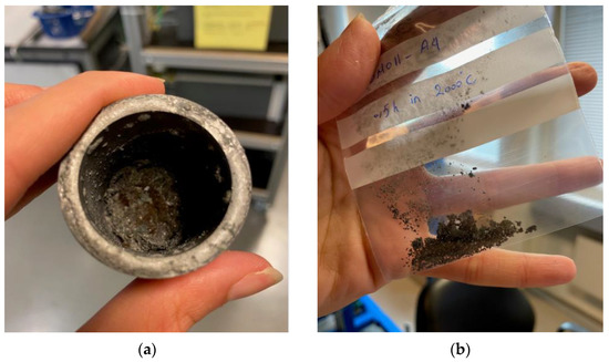
Figure 3. (a) Fused material inside the graphite crucible; (b) fused material collected from the graphite crucible.
2.4.2. Scanning Electron Microscopy (SEM) and Semi-Quantitative Analyses by Energy Dispersive X-ray Spectroscopy (EDS)
After cooling to room temperature, the remaining material was removed from the graphite crucible, and image analyses were carried out in an ULTRA 55 microscope (Zeiss, NTNU, Trondheim, Norway).
Through the results obtained in semiquantitative analysis of SEM/EDS it is possible to determine the composition of the individual phases present; metallic, carbonaceous or slag. By confronting the results of mass or atomic composition of Si of the metallic phases obtained by EDS analysis, it would be possible to relate them to the information provided by the Fe-Si diagram, and thus confirm the presence of the respective metallic phase (Si; FeSi and FeSi2).

